
TM 10-5410-221-14/1
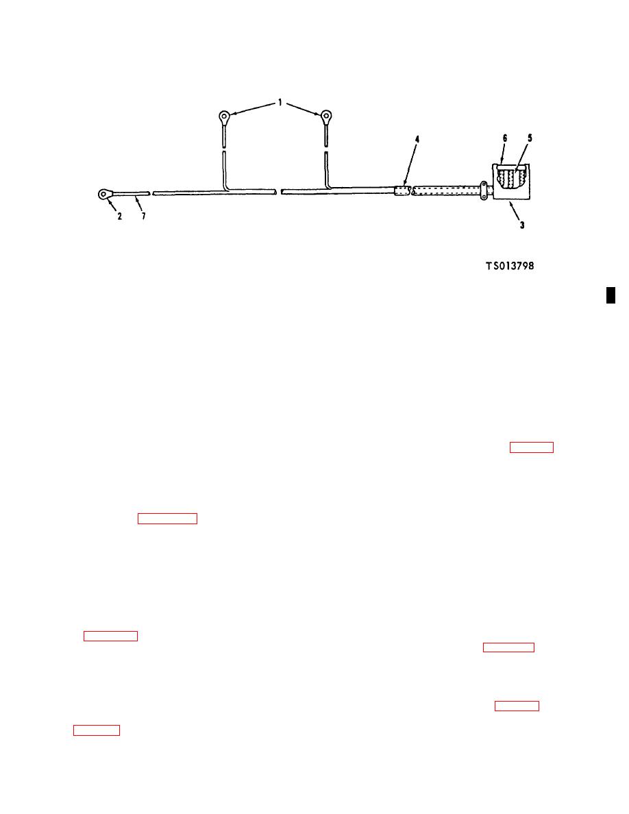
1. Terminal (2)
3. Hood
5. Sleeving, insulation
7. Wire
2. Terminal (1)
4. Sleeving, insulation
6. Receptacle
Figure 6-13. Fluorescent Light Female Harness Assembly, Disassembly (TS 013798)
wires (7) from receptacle (6). Remove sleeving (4 and
fittings on individual wires. Continuity must not exist
5).
between connector pins and connector shell.
If
d. Repair. Inspect wires and insulation sleeving for
continuity does not exist between end fittings on
individual wires, replace wire or connector.
abrasions and cuts. Minor cuts and abrasions are
g. Installation. Install female harness assemblies as
acceptable and may be repaired by wrapping with vinyl
follows:
tape. Replace individual wires if cut or otherwise
(1) Install the harness assemblies (11 and 12,
damaged.
FO-3) (located in back of manual) to electrical wiring
NOTE
raceways.
Cuts
or
abrasions
of
harness
(2) Connect terminals (1 and 2, fig. 6-13) to light
assemblies may be due to sharp edges
and switch.
of electrical raceways, interference with
(3) Install screws (3) and yoke (4) and install
other components or improper handling.
harness assemblies (11 and 12, FO-3) (located in back
The cause shall be determined and
of manual) to junction box. Install screws (1) and install
eliminated before installation of the
cover plates (2) (4) Connect harness assemblies (11and
harness assemblies.
12, FO-3) to receptacle boxes located on the shelter
e. Assembly. Using figure 6-13 as a guide, assemble
ceiling.
the light wiring harness as follows:
(1) Install insulation sleeving (4 and 5) over wires
6-10. Florescent Light Male Harness Assemblies
(7) and push back to expose connection end. Solder
a.
General.
The male fluorescent light harness
wires (7) to receptacle (6) according to Specification
assemblies (13 and 14, FO-3) (located in back of
M1LS-6872 using Sn60 solder that conforms to Federal
manual) consist of a male connector and three electrical
Specification QQ-S-571. Slide insulation sleeving (4 and
leads.
5) over soldered connection points.
b. Removal.
NOTE
(1) Disconnect harness connectors (13 and 14,
Install wires on connector pins according
FO-3) from receptacle boxes on the shelter ceiling.
to figure 6-13: If wires are replaced, mark
(2) Remove screws (1, fig. 6-14) and cover
wire location number from removed wire
plates (2) from receptacle boxes and remove screw (3)
onto replacement wire.
and bracket (4). Separate male harness (8) from
(2) Install terminals (1 and 2) on wires and crimp
bracket (4) by removing nut (5), washer (6) and screw
to secure.
(7).
(3) Install hood (3) on receptacle (6).
(3) Disconnect terminals (1, fig. 6-15) from light
f. first. Use a continuity light, multimeter (para 11-2) or
assemblies.
other continuity checking device to check continuity of
wiring (fig. 6-13). Continuity must exist between end
Change 1, 6-21

