TM 10-5410-221-14/1
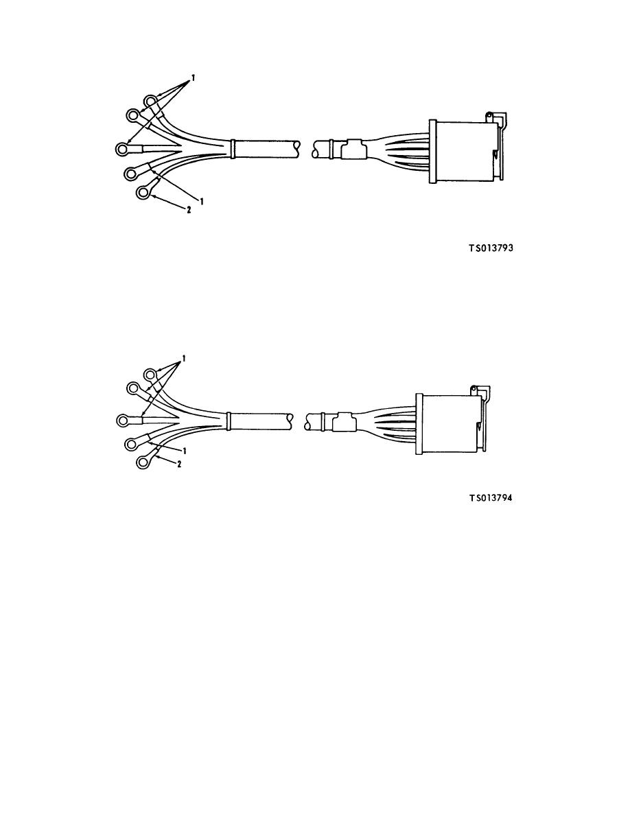
1. Terminal (4)
2. Terminal (1)
Figure 6-8. 400 Hertz Power Out Harness Assembly (TS 013793)
1. Terminal (4)
2. Terminal (1)
Figure 6-9. 60 Hertz Power In Harness Assembly (TS 013794)
or other continuity checking device to check wiring
Replace harness assembly if individual wires are cut or
continuity. Continuity must exist between connector pins
otherwise damaged.
and corresponding terminal. Continuity must not exist
NOTE
between connector pins or between connector pins and
Cuts or abrasions of harness assemblies
connector shell. If test indicates a defective connector or
may be due to sharp edges of electrical
wires, replace harness assembly.
raceways,
with
other
e. Installation. Install 60 Hertz power harness
components or improper handling. The
assembly as follows:
cause shall be determined and eliminated
(1) Install the nuts, washers and screws to secure
before installation of the harness
the 60 Hertz harness and connector assembly (1, FO-3)
assemblies.
(located in back of manual) to the power inlet panel.
6-17