
TM 10-5410-221-14/1
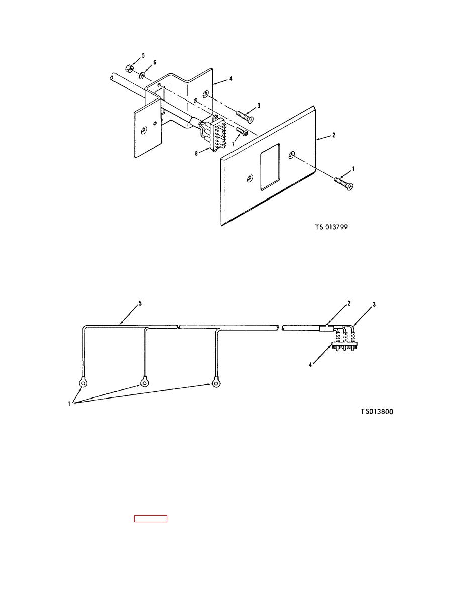
1.Screw (2)
3. Screw (2)
5. Nut (2)
7. Screw (2)
2. Cover plate
4. Bracket
6. Washer (2)
8 Male fluorescent harness connector assembly
Figure 6-14. Fluorescent Lights Receptacle Box. Disassembly (TS 013799)
1. Terminal (3)
3. Sleeving. Insulation
4. Connector
5. Wire
2. Strap. identification
Figure 6-15. Fluorescent Light Male Harness Assembly (TS 013800)
(4) Pull harness assemblies (13 and 14, FO-3)
(3) Slide insulation sleeving (3) back to expose
(located in back of manual) from the electrical wiring
soldered wire connections to connector(4). Unsolder
raceways.
connections and remove wires (5) from connector.
c. Disassembly.
Remove sleeving (3).
d. Repair. If possible, straighten any bent connector
(1) Remove terminals (1, fig. 6-15).
pins. Inspect wires for abrasions and cuts of
(2) Remove identification strap (2).
6-22

