TM 9-4931-374-13&P
2-4. ASSEMBLY AND PREPARATION FOR USE (cont)
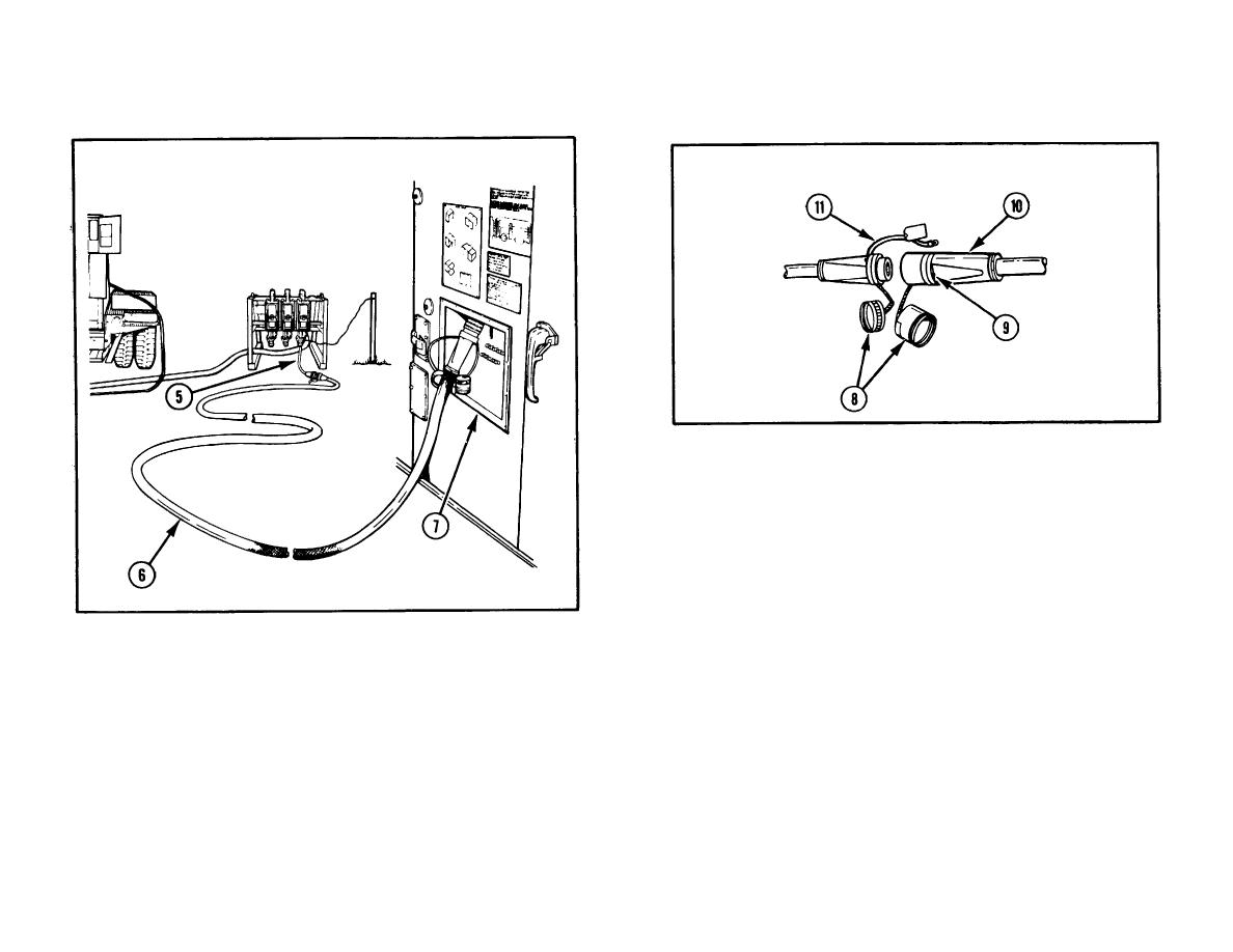
(5) Remove dust covers (8) from all connectors and join all
connectors.
(6) Remove existing screw (9) from male connector (10) of
120/208V cable assembly.
(7) Replace screw (9) using it to attach cable assembly (11) to
male connector (10).
(8) Check that all circuit breakers in circuit breaker panel box, to
the right of personnel door, are in the ON position.
NOTE
One or two 120/208V cable assemblies may be used as
WARNING
required.
Ensure grounding rod is installed and connected before
(4) Lay out two 120/208V cable assemblies (6) between cable
energizing shop set.
adapter assembly (5) and connector J1 of power input panel
(7) on the exterior of the shelter (personnel door end).
(9) Energize shop set by placing circuit breaker on power
distribution panel connected to power source in ON position.
2-14


