TM 9-2330-390-14&P
5-6.
HYDRAULIC CONTROL VALVE REPAIR (Con’t).
NOTE
Steps 3 through 6 are performed the same way for the positioning cylinders work
section and the lift cylinder work sections. Positioning cylinders work section is
illustrated.
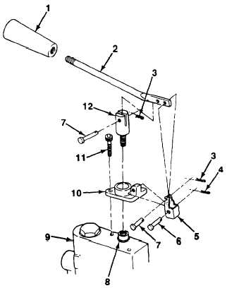
3.
If removed, install spool end adapter (12) on spool valve (8). Install clevis (10) on positioning cylinders work
section (9) with two capscrews (11). Torque capscrews to 110-130 lb.-in. (12-15 N•m).
4.
Install link (5) on clevis (10) with clevis pin (6) and cotter pin (4).
5.
It removed, apply sealing compound on handle (2) and install knob (1).
6.
Install handle (2) on link (5) and spool end adapter (12) with two clevis pins (7) and cotter pins (3).
Follow-on Tasks:
l
Install hydraulic control valve (see paragraph 4-108).
5-19