TM 9-2330-390-14&P
2-12.
ATTACHlNG FRONT AND REAR DOLLIES TO SHELTER (SHELTER ON GROUND)
(SIDE LIFT OPERATION) (Con't).
j.
Remove detent pin (19) securing each crossbrace assembly (16) in retracted position. Extend
crossbrace assembly until two holes aline. Install detent pin (19) and detent pin (20) that was removed from storage
box.
k.
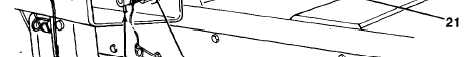
Extend crossbrace assemblies (16) over top of shelter (6). Crossbrace bracket (21) at each end of
crossbrace assembly should be positioned flush against top beam (2). Operate hydraulic control valve as required to
achieve proper alinement (see paragraph 2-21).
Use extreme caution when installing twist locks. Keep hands and/or feet clear of top
hooks, top and bottom beams, and from between beams and shelter. Failure to follow
this warning may cause serious injury to personnel.
l.
At front and rear, install two twist locks (18) through slots in top beam (2). Rotate twist locks 90° and
insert through crossbrace brackets (21). Rotate twist locks 90° again. Locate twist locks so that they are against top of
slots in top beam. Use twist lock wrench (Item 3, Appendix D) to fully tighten nuts (22). Ensure that twist lock pins (24)
are vertical. Safety pins (23) do NOT need to be installed through twist locks.
m. Loop and secure two slings (28) to each axle (25), as illustrated. On front dolly, position slings between
tie-down D-rings (27) and steering stops (26). On rear dolly, position slings between tie-down D-rings and pintle
assembly approximately 10 in. (25.4 cm) off centerline to each side.
n. Lay out chain assembly at each comer of shelter (6).
2-88