
TM 10-8340-243-13&P
0005
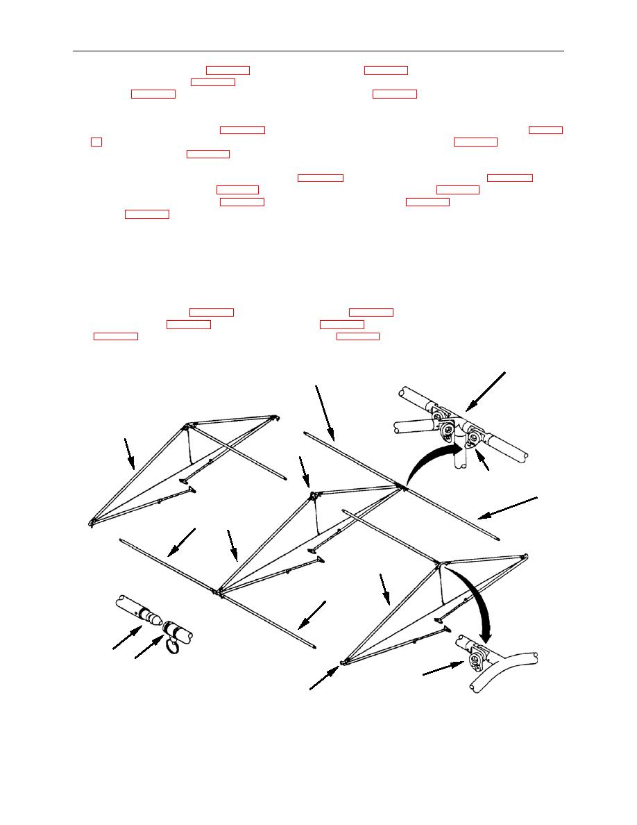
5. Unfold the four left hand (Figure 4, Item 7) and right hand (Figure 4, Item 8) purlins on the center
wall frame assembly (Figure 4, Item 2). Lock these into place by engaging the teeth and turning the
handles (Figure 4, Item 6) on the midwall fitting assemblies (Figure 4, Item 9) towards the center.
When viewed from above, this piece would appear in the shape of an "H".
6. Rotate the left hand purlins (Figure 4, Item 7) on the center of each end wall frame assembly (Figure
4, Item 1) so they are pointing into the air, and lock into place with the handle (Figure 4, Item 6) on
the end peak fitting (Figure 4, Item 5).
7. Rotate one of the end wall frame assemblies (Figure 4, Item 1) so the connector end (Figure 4, Item
10) of the left hand purlin (Figure 4, Item 7) is facing the peak center joint (Figure 4, Item 5) of the
socket (Figure 4, Item 11). It should lock into place. Repeat this procedure with the other end wall
frame assembly.
NOTE
If the connector does not fit in easily, do not force it. Pull the pin and wiggle the connector
into the socket.
8. Connect the left hand (Figure 4, Item 7) and right hand (Figure 4, Item 8) purlins on the center wall
frame assembly (Figure 4, Item 2) to the sockets (Figure 4, Item 11) on the end wall corner fittings
(Figure 4, Item 12) of the end wall frame assemblies (Figure 4, Item 1). Lock all four purlins in the
same manner.
9
7
1
5
6
8
7
2
1
8
10
11
6
12
END OF TASK
