TM 10-5411-200-14
T.O. 35E4-177-1
5-3. (cont)
3.
Inspect for and replace if necessary:
a. Hissing or damaged components.
b. Corrosion or paint damage.
REPAIR
Repair corrosion or paint damage. (Refer to paragraph 4-43)
ASSEMBLY
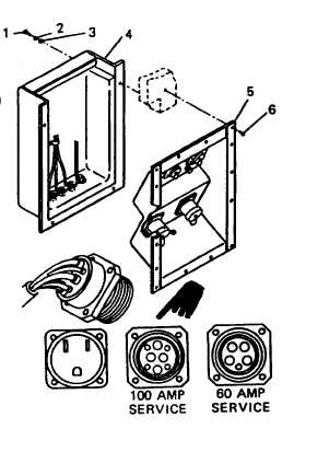
1.
Install threaded stud (22), terminal lug (21), three washers (20),
three lockwashers (19), and four nuts (18) in panel (8).
2.
Install binding post body (28), nylon washer (27), two O-rings (26),
nylon washer (25), brass washer (24), lockwasher (17), nut (16), and
rubber cap (15) in panel (8).
3. Using crimping tool, attach wires to receptacle pins. (Refer to
paragraph 4-46).
4.
Install receptacles (13 and 14) in panel (8) and secure with screws
(9), lockwashers (10), receptacle covers (11), washers (23), and nuts
(12).
5.
Install receptacles (5 and 6) and gaskets (7) in panel (8) and secure
with screws (l), lockwashers (2), receptacle covers (3), and nuts (4),
INSTALLATION
1.
Position power entry panel assembly
(5) against outside-of personnel door
end endwall panel and secure with
rivets (6). (Refer to paragraph 4-32)
2. Connect wires to receptacles and
terminals/connectors at rear of
power entry panel assembly (5).
(Refer to paragraph 4-46)
3. Position cover assembly against
inside of personnel door end
endwall panel and secure with
screws (1), lockwashers (2), and
4.
washers (3).
Reconnect electrical power to
service entrance receptacle.
CHANGE 2
5-7