
TM 9-4931-374-13&P
3-27. WIRING HARNESS ASSEMBLY (CEILING)--MAINTENANCE INSTRUCTIONS (cont)
INITIAL SETUP:
References
any maintenance on the harness assem-
Appendix C
bly, be sure the circuit breaker on the
Appendix D
power distribution panel connected to
Appendix E
power source is in OFF position and the
3-74
Wire table.
120/208V cable assembly is disconnected
3-46
Disassembly procedure for electrical
from the shop set.
installation.
3-46
Reassembly procedure for electrical
NOTE
installation.
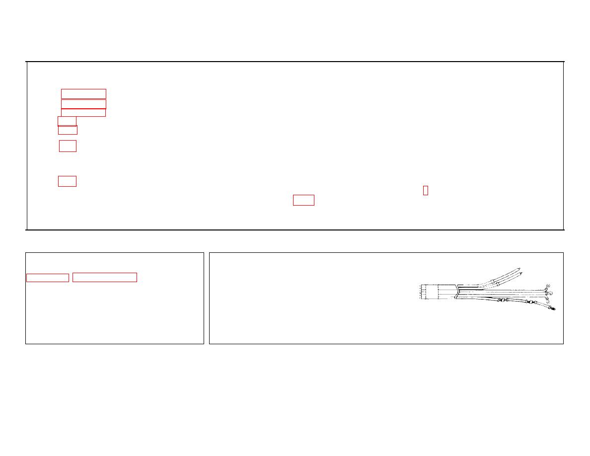
The harness assembly is comprised of ten
wire sections of various lengths. All
Troubleshooting Reference
sections are tagged with the following
3-7
There is no electrical power at outlets.
numbers: no. 4, no. 5, no. 6, no. 9, no.
10, and no. 11. (Refer to wire table, p
WARNING
3-74.) Four wire sections were removed
The shop set contains voltages which are
separately and six were removed together.
dangerous if contacted. Before performing
REMOVAL
INSPECTION
For removal procedures for the harness
assembly, refer to disassembly procedure on
ALL WIRE SECTIONS.
page 3-46, paragraph 3-10, for electrical
installation.
a. Check for breaks, corrosion, and worn
or deteriorated insulation.
b. Check for continuity with a suitable
3-228
