TM 9-2330-390-14&P
4-60. SPIDER ASSEMBLY REPLACEMENT.
This Task Covers:
a.
Removal
b. Cleaning and lnspection
C.
Installation
Initial Setup:
Equipment Conditions:
Materials/Parts:
• Air lines disconnected from airbrake chamber (see
• Wire brush (Item 4, Appendix F)
paragraph 4-72 or 4-73).
• Silicone compound (Item 12, Appendix F)
• Brakes caged (rear dolly) (see paragraph 4-56).
• Detergent (Item 13, Appendix F)
• Hub and brakedrum removed (see paragraph 4-75).
• Grease (Item 19, Appendix F)
• Brakeshoes removed (see paragraph 4-57).
• Rags (Item 25, Appendix F)
Tools/Test Equipment:
• General mechanic’s tool kit (Item 30, Appendix G)
• Compressor unit (Item 4, Appendix G)
• Dry cleaning solvent (Item 27, Appendix F)
• Fourteen lockwashers
General Safety Instructions:
• Dry cleaning solvent is flammable and must not be used near an open flame. Use only in a well-ventilated area.
• Compressed air used for cleaning purposes should never exceed 30 psi (207 kPa).
NOTE
Front and rear dolly spider assemblies are replaced the same way. Rear dolly spider
assembly is Illustrated.
a.
REMOVAL
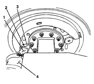
1.
2.
Loosen spanner nut (2) on housing assembly
tube (1) of airbrake chamber (4).
Remove airbrake chamber (4) from plunger
housing (3).
4-131