TM 9-2330-390-14&P
4-58.
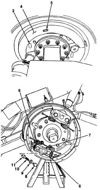
MAJOR BRAKE ADJUSTMENT (Con’t).
2.
3.
4.
5.
6.
7.
8.
Remove plugs from access slots (3). Check ad-
justing bolts to ensure they are completely bot-
tomed. If not, manually back off starwheel (6) by
turning counter clockwise to bottomed position.
Using 15-20 psi (103-138 kPa) air, pulsate air
pressure to actuate and release brakes five or six
times and observe through access slots that star-
wheel and adjusting bolt for each brakeshoe are
rotating.
Insert feeler gage into access slot (5) in top and
bottom dust shields (4). Check brakeshoe Iining-
to-brakedrum clearance at top of each brake-
shoe. Total clearance for both brakeshoes should
not exceed 0.090 in. (2.3 mm). Individual brake-
shoe clearance should not exceed 0.050 in. (1.3
mm) across width of shoe.
(a)
If clearances are within specification,
install plugs in access slots (3). Remove
temporary air hose (1) from airbrake cham-
ber (2). Proceed to step 5.
(b)
If clearances are not within specification,
proceed to step 5.
Rotate brakedrum by hand one full turn. There
should be minimal drag. If drag is apparent, pro-
ceed to step 6.
If brakeshoes have not properly adjusted, remove
hub and brakedrum (see paragraph 4-75).
Remove two guide pawl hollow capscrews (8)
copper washers (9), springs (10), and adjusting
pawls (11) from plunger housing (7).
Inspect teeth of adjusting pawls (11) for rounded
or flattened condition. If teeth are damaged,
replace spider assembly (see paragraph 4-60).
4-127