TM 10-5410-229-13&P
2-6. ASSEMBLY AND INSTALLATION INSTRUCTIONS - Cont’d
(5)
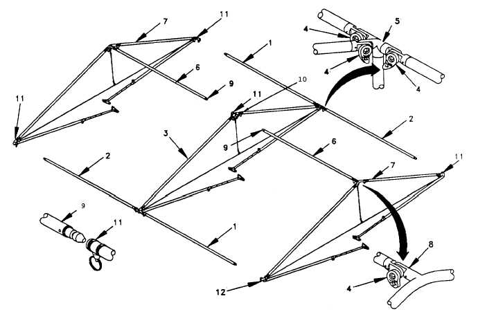
Unfold the four left hand (1) and right hand (2) purlins on the center wall frame assembly (3).
Lock these into place by engaging. the teeth and turning the handles (4) on the midwall fitting
assemblies (5) towards the center. When viewed from above, this piece would appear in the
shape of an "H".
(6)
Rotate the left hand purlins (6) on the center of each end wall frame assembly (7) so they are
pointing into the air, and lock into place with the handle. (4) on the end peak fitting (8).
(7)
Rotate one of the end wall frame assemblies (7) so the connector end (9) of the left hand
purlin (6) is facing the peak center joint (10) of the center wall frame assembly (3). Insert the
connector (9) into the socket (11). It should lock into place. Repeat this procedure with the
other end wall frame assembly (7).
2-17