TM 10-5410-229-13&P
5-11.
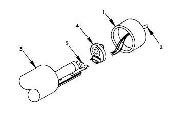
REPAIR LIGHT SET - Cont’d
NOTE
Ensure that one set of wires of same color from ballast assembly goes to closest
lampholder and one set goes to far lampholder.
(b)
If wire leads (11,12) from ballast assembly (13) were found serviceable, remove 1/4" of insulation from
the ends of the wires. Solder the wires on the ballast (13) to wires (11,12) on the extrusion assembly
(7). Apply insulation tape after the solder point cools.
(c)
If wire leads (11,12) from ballast assembly (13) were removed from the extrusion assembly (7) entirely,
install wires supplied with ballast assembly (13) onto extrusion assembly (7) and lampholders (4).
(d)
Connect AC (white) wire (9) to AC input connection and install splice (10).
(e)
Connect black wire ring terminal (8) to switch.
(f)
Ensure that extrusion assembly (7) aligns with track in luminaire (3) and ballast assembly (13) is
covered by white portion of luminaire. Slide extrusion assembly (7) into luminaire (3).
(g)
Install male end cap assembly (1) on luminaire (3). Install lamp (6).
(h)
Install lampholder (4) and female end cap (2) onto luminaire (3).
c.
Remove and Install Female Cable Assembly.
5-12