
TM 10-5410-221-14/1
b. Removal. Remove humidifier harness (16, fig. 6-
lockwashers (47) and nuts (46) on terminals 3 through 6
on terminal board (45), and terminal 2 on terminal board
7. sheet 1 of 5) according to sequence of index numbers
(38). Replace terminal board cover (42) on terminal
assigned to figure 6-7 and observing the following.
board (45) and terminal board cover (35) on terminal
(1) Open circuit breaker panel cover.
(2) Remove circuit breaker panel per paragraph 6-
board (38).
(3) Position relay (24) on mounting bracket and
21b.(2).
secure with screw (22), washer (21) and nut (20).
(3) Remove terminal board cover (42, fig. 6-7, sheet
(4) Position circuit breaker panel (123, fig. 6-7, sheet
2 of 5) and remove nut (46), lockwasher (47) and washer
5 of 5) on distribution box (124) and secure.
(48) from terminals 3 through 6 on terminal board (45).
Remove the electrical leads. Remove electrical lead
from terminal 2 on terminal board (38).
6-27.
Remote
Temperature
Sensing
Harness
(4) Remove screws (17, fig. 6-6. sheet 1 of5)and
Assembly
(disconnect electrical leads from circuit breaker (10)7,
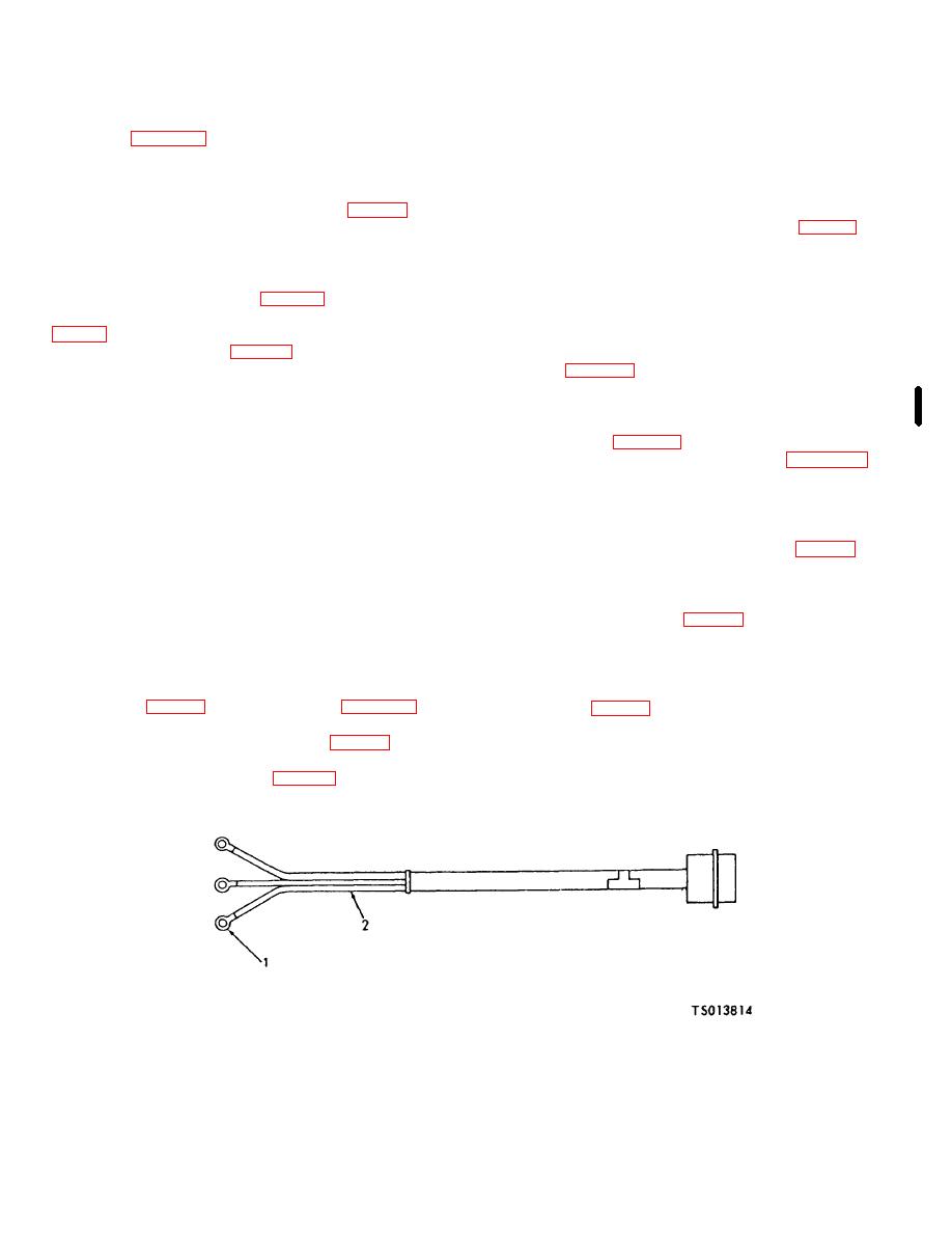
a. General. The remote temperature sensing
(5) Remove nut (20. fig. 6-7 sheet 2 of 5), washer
harness consists of a connector and three electrical
(21) and screw (22) used to secure relay (24) to
leads (2, fig. 6-29)' to provide interconnection between
mounting bracket.
the electrical- system and a remote temperature probe.
(6) Remove nut (12, fig.6-7. sheet 1 of 5), washer
This harness is installed on shelter No. 1 thru 184 only.
(13) and screw (14) used to secure humidifier harness
b. Removal Remove remote temperature harness
(16) (humidistat receptacle) to distribution box. Remove
assembly (72, fig. 6-7. sheet 2 of 5) according to
receptacle cover (15).
sequence of index numbers assigned to figure 6-7 and
(7) Remove the humidifier harness assembly (16)
observing the following:
from the distribution, box.
(1) Open circuit breaker panel cover.
c. Test. Use a continuity light, multimeter (para 11-
(2) Remove -circuit breaker panel per paragraph 6-
2) or other continuity checking device to check continuity
211b2).
of wiring. Continuity must exist between end fittings on
(3) Remove terminal board cover (65, fig. 6-7, sheet
individual wires. Replace harness assembly if continuity
2 of 5) and remove nut (69). lockwasher (70) and
does not exist or relay is defective.
washer (71) from terminals: 1 through 3 on terminal
d. Repair. Inspect wires for abrasions and cuts of
board (68). Remove the electrical leads.
insulation. Minor cuts and abrasions are acceptable and
(4) Remove nuts (80. fig. 6-7, sheet 3 of 5). ( 81 )
may be repaired by wrapping with vinyl tape. Replace
and screws (82) to remove connector (84) from the
harness assembly if individual wires are cut or otherwise
distribution box. Remove connector cover (8;3) from
damaged or relay is damaged or defective.
connector.
c. Installation. Install the humidifier harness
(5) Remove the remote temperature sensing
assembly (16, fig. 6-7, sheet I of 5) using figure 6-7 as a
harness (72, fig. 6-7. sheet'2 of 5) from the distribution
guide and observing the follows:
box.
(1) Position harness assembly (16, fig. 6-7, sheet 1
of 5) in distribution box and install electrical leads.
(2) Replace washers (48, fig. 6-7, sheet 2 of 5),
1. Terminal (3)
2. Electrical leads (3)
Figure 6-29.RFremote Temperature Wiring Harness (TS013814)
Change 1 6-40

