
TM 10-5410-221-14/1
c.
Disassembly.
Disassemble the remote
provide for interconnection of the power distribution box
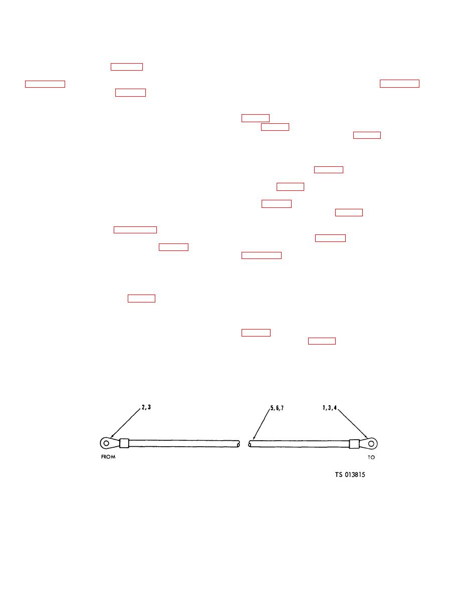
electrical system. The wire and terminal assemblies
temperature sensing harness to replace damaged parts
consist of a single wire with a terminal lug on each end.
by removing terminals (1, fig. 6-29).
b. Removal. Remove loose wires according to
d. Assembly. Assemble harness assembly using
sequence of index numbers assigned to figure 6-7 and
observing the following.
(1) Install terminals (1, fig. 6-29).
(1) Open circuit breaker panel cover door.
(2) Crimp to secure.
e. Test. Use a continuity light, multimeter (para 11-
(2) Remove screw to disconnect electrical wire (88,
2), or other continuity checking device to check continuity
(107, fig. 6-7, sheet 5 of 5). Disconnect other end of wire
of wiring. Continuity must exist between end fittings on
from terminal 2 toggle switch (85, fig. 6-7, sheet 3 of 5).
individual wires. Continuity must not exist between
(3) Disconnect wires (86 and 87) from toggle
connector pins or between connector pins and connector
switches (85).
shell. Replace harness assembly if continuity tests
(4) Disconnect wires from terminals 1, 3 and 5 of
indicates defective wires or connection.
circuit breaker (101, fig. 6-7, sheet 5 of 5). Disconnect
f. Repair. If possible, straighten any bent connector
other end of wires from terminals 2, 3, and 4 on terminal
pins. Inspect wires for abrasions and cuts of insulation.
board (60, fig. 6-7, sheet 2 of 5).
Minor cuts and abrasions are acceptable and may be
(5) Disconnect wire from terminal 2 of circuit breaker
repaired by wrapping with vinyl tape. Replace harness
(122, fig. 6-7, sheet 5 of 5). Remove other end of wire
assembly if individual wires are cut or otherwise
from terminal 2 of lamp (79, fig. 6-7, sheet 3 of 5).
damaged.
c. Disassembly. Disassemble wire assemblies as
g. Installation. Install the remote temperature
required to replace damaged components by removing
sensing harness using figure 6-7 as a guide and
terminals (1, 2 3 or 4, fig. 6-30).
observing the following:
d. Assembly. Assemble wire assemblies using
(1) Position harness assembly (72, fig. 6-7, sheet 2
of 5) in distribution box and install electrical leads.
(1) Install terminals (1 through 4).
(2) Replace washers (71), lockwashers (70), and
(2) Crimp to secure.
nuts (69) on terminals 1 through 3 of terminal board (68).
e. Test. Use a continuity light, multimeter (para 11-
Replace terminal board cover (65) on terminal board
2), or other continuity checking device to check continuity
(68).
of wires. Continuity must exist between fittings on wires.
(3) Position connector (84, fig. 6-7, sheet 3 of 5) into
f. Installation. Install wire and terminal assemblies
mounting hole on distribution box and secure with
as follows:
screws (82), washers (81), and nuts (80).
(1) Install other end of wire to terminal 2 of lamp (79,
(4) Place circuit breaker panel in position on
distribution box and secure with screws.
circuit breaker (122, fig. 6-7, sheet 5 of 5).
6-28. Wire and Terminal Assemblies
a.
General.
The wire and terminal assemblies
1. Terminal (3)
3. Terminal (6)
5. Wire
7. Wire
2. Terminal 3)
4. Terminal (2)
6. Wire
Figure 6-30. Wire and Terminal Assemblies (TS 013815)
6-41

