TM 9-2330-390-14&P
5-5.
SUSPENSION LINK REPLACEMENT (Con't).
5.
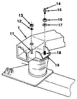
Lower suspension link (1) until studs (11 and 18)
are positioned through holes in suspension link
mounting plate (19).
6.
Install two flatwashers (12 and 17) and new iock-
nuts (13 and 16) on studs (11 and 18). Torque
locknuts to 25 lb.-ft (34 N•m).
7.
Install valve (15) on stud (18) with sealing com-
pound (see paragraph 4-16). install cap (14) on
valve.
8.
If a front suspension link was removed, install
brace (see paragraph 4-94).
9.
If front or rear left side suspension link was
removed, install hydraulic control valve bracket
with associated components (see para-
graph 4-93 or 4-96).
10.
If front or rear right side suspension link was
removed, install junction box bracket with asso-
ciated components (see paragraph 4-92 or 4-95).
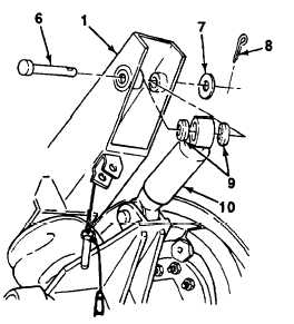
11.
install shock absorber (10) and two bushings (9)
on suspension link (1) with clevis pin (6) flat-
washer (7) and new cotter pin (8).
5-13