TM 9-2330-390-14&P
4-54.
STEERING KNUCKLE ASSEMBLY REPLACEMENT.
This Task Covers:
a.
Removal
b. Cleaning and Inspection
C.
Installation
Initial Setup:
Equipment Conditions:
Materials/Parts:
•Hub and brakedrum removed (see paragraph 4-75).
•Front dolly air line disconnected from airbrake
chamber (see paragraph 4-72).
Tools/Test Equipment:
•General mechanic’s tool kit (Item 30, Appendix G)
•Compressor unit (Item 4, Appendix G)
•Torque wrench, 0-175 lb.-ft. (Item 42, Appendix G)
• Grease (Item 19, Appendix F)
• Dry cleaning solvent (Item 27, Appendix F)
• One roll pin
• One thrustwasher
• Two grease fittings
• Two welch plugs
• Eight lockwashers
Personnel Required: Two
General Safety instructions:
• Dry cleaning solvent is flammable and must not be used near an open flame. Use only in a well-ventilated area.
• Compressed air used for cleaning purposes should never exceed 30 psi (207 kPa).
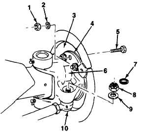
a . R E M O V A L
1.
Remove eight nuts (1), lockwashers (2), cap
screws (5), and spider assembly (3) with
brakeshoes and wedge brake components from
spindle (4) of steering knuckle assembly (6). Dis-
card lockwashers.
2.
Remove circle cotter (7), hex castle nut (8), and
flatwasher (9) from tie-rod (10) and steering
knuckle assembly (6).
3.
Separate tie-rod (9) from steering knuckle assem-
bly (6).
4-116