
TM 10-5410-221-24
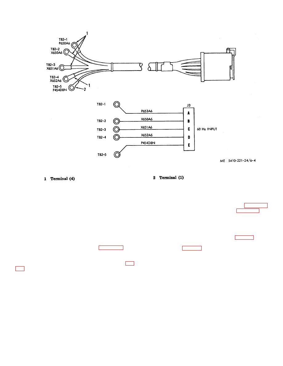
Figure 6-4. 60 Hertz power in harness assembly.
g. Installation. Install 60 Hertz power harness
if individual wires are cut or otherwise damaged.
assemblies in reverse order of removal using figure 6-5
Note. Cuts or abrasions of harness assemblies
as a guide for terminal identification and figure 1-7 for
may be due to sharp edges of electrical raceways,
wiring schematic.
interference with other components or improper
6-8.
Surgical and Air-Lock Lights Harness and
handling. The cause shall be determined and eliminated
Connector Assembly
before installation of the harness assemblies.
a. Removal.
(1) Disconnect terminals (1, 2, fig. 6-6) from
e. Assembly. Assemble power harness assembly
terminal boards TB3, TB4, and TB5 inside power
in reverse order of disassembly using figure 6-5 as a
distribution box (fig. 6-22, items 28, 38, 45).
guide) install terminals (1, 2) and crimp to secure.
(2) Remove cover from raceway adjacent to
f.
Test. Use continuity light, multimeter, or other
power out panel and remove clamps securing the
continuity checking device to check wiring continuity (fig.
harness to the raceway.
corresponding terminal.
Continuity must not exist
Note. Tag or otherwise identify electrical leads as to
between connector or between connector pins and
connection point for aid at installation.
connector shell. If test indicates a defective connector or
wires, replace harness assembly.
(3) Remove nuts, washers and
screws
securing the surgical and air-lock lights harness
6-5
