TM 9-2330-390-14&P
Section V. SPECIAL PURPOSE KITS MAINTENANCE
Paragraph
Number
5-9
5-10
5-11
Paragraph Title
Side Lift Kit Installation . . . . . . . . . . . . . . . . . . . . . . . . . . . . . . . . . . . . . . . . . . . . . . . . .
Hydraulic Lift Cylinder Repair (M1022Al With Side Llfl Kit)
. . . . . . . . . . . . . . . . . . . .
Hydraulic Positioning Cylinder Repair (M1022Al With Side Lift Kit)
. . . . . . . . . . . . .
Page
Number
5-31
5-34
5-48
5-9.
SIDE LIFT KIT INSTALLATION.
This Task Covers: Installation
initial Setup:
Tools/Test Equipment:
l
General mechanic’s tool kit (Item 30, Appendix G)
Personnel Required: Three
NOTE
All components of ride Iift kit are listed under Functional Group Code 33, Special
Purpose Kits, in Appendlx C of this manual.
1.
Remove all side lift kit components from packing
containers. Inspect for damage.
2.
Check side lift kit items against packing slip to
ensure that all components are present.
NOTE
Perform steps 3 through 8 on front and rear
dollies.
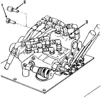
3.
4.
Remove relief valve cartridge (2) from bottom of
positioning cylinders work section (3) at hydraulic
control valve. Install side lift kit relief plug (1).
Remove positioning cylinders and lift cylinders
(see paragraphs 4-83 and 4-110).
5-31