TM 9-2330-390-14&P
4-131. STARTER SWITCH ASSEMBLY REPLACEMENT (Con’t).
2.
3.
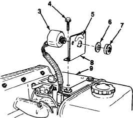
Remove round nut (7), spacer (6) and starter
switch (3) from case (8).
Remove two flange bolts (4) and case (8) from oil
cooler cover (9).
1.
If label (5) on case (8) is missing or illegible, replace label (see paragraph 4-106).
2.
Install case (8) on oil cooler cover (9) with two flange bolts (4).
3.
Install starter switch (3) on case (8) with key indexed to notch in case.
4.
Install spacer (6) and round nut (7) on starter switch (3).
5.
Connect wiring harness connector (2) to starter switch connector (1). Install new tie-down strap.
Follow-on Tasks:
Connect negative (-) ground cable to battery (see paragraph 445).
Start engine (see paragraph 2-20) and check operation of engine.
4-385

