TM9-2330-390-14&P
4-109. HYDRAULIC LINES REPLACEMENT (Con't).
2.
3.
4.
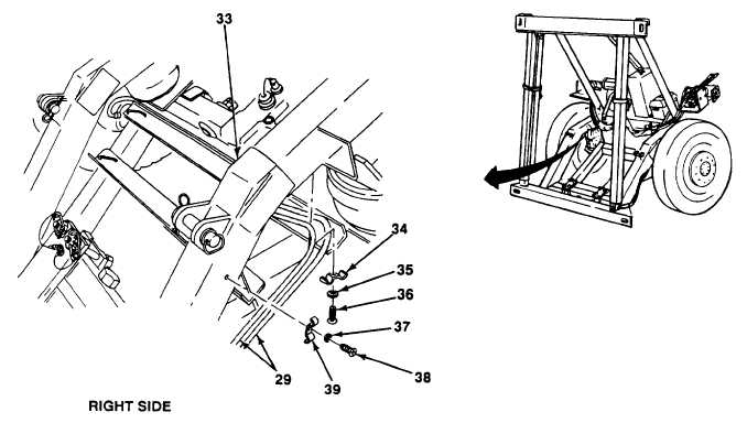
Remove self-tapping screw (38), flatwasher (37), and hose clamp (39). Releasetwo hose assemblies (29) from
side of suspension link (33).
NOTE
Perform steps 3 and 4 only if removing hose assembly to a far (right side) hydraulic
positioning cylinder.
Remove self-tapping screw (36), flatwasher (35), and hose clamp (34). Releasetwo hose assemblies (29) from
underside of suspension link (33).
Release hose bundle from supported position. Remove tie-down straps from abrasion sleeve (10). Discard
tie-down straps.
NOTE
Front and rear dolly hose assemblies are connected to hydraulic control valve the
same way. Front dolly Is illustrated.
5.
Disconnect hose assembly (29) from swivel nut elbow (40) or swivel nut tee (41) at positioning cylinders work
section (42) of hydraulic control valve (8).
4-298 Change 1