TM 9-2330-390-14&P
4-68.
REAR DOLLY SHUTOFF VALVE AND MOUNTING BRACKET REPLACEMENT.
This Task Covers:
a.
Removal
b.
Installation
initial Setup:
Equipment Conditions:
l Wheels chocked.
l Air reservoir drained (see paragraph 3-6).
Materials/Parts:
l Antiseize tape (Item 29, Appendix F)
Tools/Test Equipment:
l General mechanic’s tool kit (Item 30, Appendix G)
l Adjustable wrench (Item 37, Appendix G)
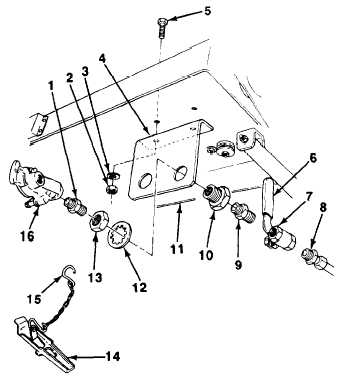
NOTE
Both rear dolly shutoff valves are replaced the same way. Right side (service) shutoff
valve is illustrated.
1.
Disconnect tube assembly (8) from shutoff valve
(7)
2.
Remove shutoff valve (7) from reducer (9).
NOTE
Perform steps 3 through 8 only if reducer,
anchor coupling, or mounting bracket are
damaged.
3.
4.
5.
6.
7.
8.
Remove reducer (9) from anchor coupling (10).
Remove dummy coupling (14) from gladhand
(16).
Unbend S-hook (15) and remove dummy
coupling (14) from nipple (1).
Remove gladhand (16) and nipple (1) from anchor
coupling (10).
Remove nut (13), star-washer (12), and anchor
coupling (10) from mounting bracket (4).
Remove two locknuts (2) flatwashers (3), bolts
(5), and mounting bracket (4) from pivoting tray
(11). Discard locknuts.
4-158