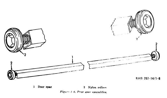
Figure 1-6. Door
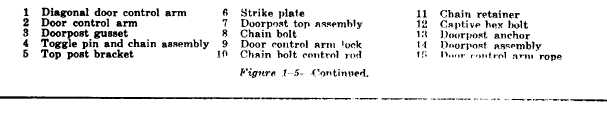
Figure 1-5--
(2) The short (4-ft) purlins (2) connect
an intermediate arch to an end arch. The stud
end of the purlin is connected to the intermedi-
ate arch; the insert end to the captive hex
bolt of the end arch. The basis of issue for
these purlins is 13 per end section.
(3) ‘l’he short (4-ft) purlins (3), both
ends of which have flanges with inserts, con-
nect the opposite end arch to the intermediate
arch. The basis of issue for these purl ins is
also 13 per end section.
(4) The end arch purlins assemblies (4)
connect the end arches to the door post assem-
blies (fig. 1-5. Both ends of these purlns
have flangeswith inserts. One end is connected
to the captive hex bolt on the door post. The
outer end receives the adjustment shaft and
clvis assembly (5, fig. 1-4) that permits the
door post to be adjusted to the proper width.
d. Doorpost Assemblies. The doorpost assem.
blies (fig. 1-5) form the frame for the vehicle
doors and assist in opening and closing them.
A right hand and left hand assembly is issued
with an end section.
(1) The top of each doorpost assembly
is connected to a movable socket on the end
arch by means of an eyebolt and an eye pin.
and chain assembly. The bottom of each door.
post assembly is connected to the end arch
by means of au end arch purlin and an ad-
justment shaft and clevis assembly.
(2) The doorpost top assembly (7), when
closed, is locked to the stationary post assembly
(14) by means of the chain bolt (8) and
strike plate (6). When opened, it pivots upward
and outward with the raised vehicle door to
provide the clearance necessary to bring equip-
ment, into the tent. It is opened by releasing
1-7