
TM 10-5410-221-14/1
Section VII. MAINTENANCE OF ELECTRICAL SYSTEM
4-18. General
4-19. 60 Hertz and 400 Hertz Power Input Cable
Assemblies
This section provides instructions for repair and
replacement of those items considered as part of the
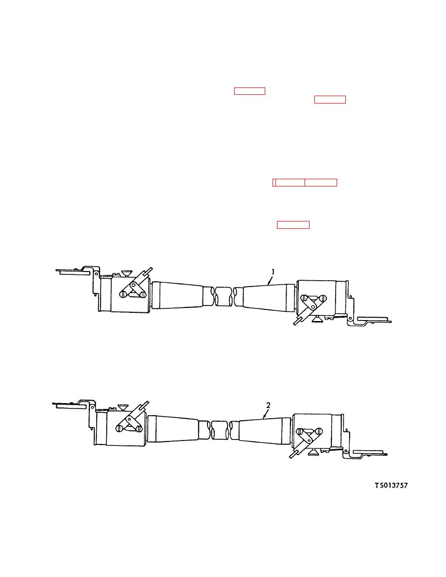
a. Removal. Disconnect cable assemblies (1 and 2,
electrical system. The electrical system consists of a
power distribution box assembly, a 60 Hertz power input
outlet panel assemblies (fig. 4-14).
cable assembly, a 400 Hertz power input cable
b. Cable Assembly Test. Check continuity of cable
assembly, an air-lock light assembly, twelve convenience
assembly wires using a continuity light, multimeter, or
receptacles, six fluorescent lamps assemblies, power
other continuity checking device. Continuity must not
input and output panels and a light switch.
exist between terminals and connector or between wires.
WARNING
Continuity must exist between connectors (wire terminal
Personnel must observe extreme cau-
to wire terminal).
If continuity check indicates a
tion to avoid contact with electrical
damaged or defective cable, replace cable.
circuits when power source is con-
c. Installation Connect cable assemblies (1, 2, fig. 4-
nected. In case of accident from elec-
13) to power source and to power inletor outlet panel
trical shock, disconnect power source at
assemblies (fig. 4-14 and 4-15).
once.
If power source cannot be
disconnected, free victim from live
4-20. Air Lock Light Assembly
conductor with a board or other non-
conductor. If victim is unconscious,
a. Removal. Disconnect cable assembly for light
apply artificial respiration and obtain
assembly (5, fig. 4-16) from air lock light receptacle on
medical help.
power inlet or outlet panel and remove light assembly
from hook in air lock chamber.
1. 60 Hertz power cable assembly
2. 40( Hertz power cable assembly
Figure 4-13. Electric Power Cable Assemblies
(TS 013757)
4-67
