
TM 10-5410-221-24
Note. Cuts or abrasions of harness assemblies
(3) Disconnect the electrical leads from
terminals 1 through 5 of TB1 terminal board in the power
may be due to sharp edges of electrical raceways,
distribution box (fig. 6-22, item 52).
interference with other components or improper
(4) Remove the nuts, washers, and screws
handling. The cause shall be determined and eliminated
securing the harness and connector assembly (2, fig. 6-
before installation of the harness assemblies.
d. Assembly.
Assemble power harness
assembly from the shelter.
assemblies in reverse order of disassembly using figures
b. Disassembly. Disassemble power harness
assemblies as required to replace damaged terminals
to secure.
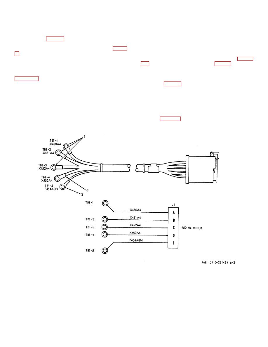
e. Test. Use a continuity light, multimeter, or
according to sequence of index numbers assigned to
other continuity checking device and check wire
electrical leads.
continuity (fig. 6-2). There must be continuity between
c. Repair.
If possible, straighten any bent
corresponding terminals and connector pins. Continuity
connector pins. Inspect wires for abrasions and cuts of
must not exist between pins or between pins and
insulation. Minor cuts and abrasion are acceptable and
connector shell. If test indicates a defective connector,
may be repaired by wrapping with vinyl tape. Replace
replace harness and connector assembly.
f.
Installation. Install 400 Hertz harness and
harness assembly if individual wires are out or otherwise
damaged.
connector assembly in reverse order of removal
observing figure 6-2 as a guide for
Figure 6-2. 400 Hertz power is harness assembly.
6-2

