TM 9-4931-374-13&P
NOTE
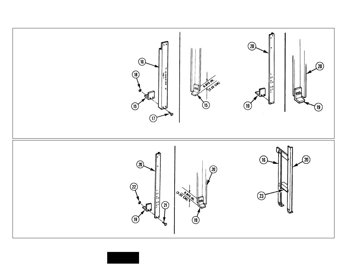
When bolted together, the
bottom of angle (15) should
extend below the bottom of
front right-hand angle (16) as
illustrated.
10
TWO BOLTS (17) AND TWO NUTS (18).
Install so that center line of two bolts (17)
is approximately 0.875 in. (2.22 cm) from
bottom of angle (15) as illustrated.
11
ANGLE (19). Position long leg against long
leg of rear right-hand angle (20) as
illustrated.
NOTE
When bolted together, the
bottom of angle (19) should
extend below the bottom of
rear right-hand angle (20) as
illustrated.
12
TWO BOLTS (21) AND TWO NUTS (22).
Install so that center line of two bolts (21)
is approximately 0.875 in. (2.22 cm) from
bottom of angle (19) as illustrated.
13
ANGLE (23). Position long leg on long legs
of front right-hand angle (16) and rear
right-hand angle (20) as illustrated.
3-259


