
TM 9-4931-374-13&P
3-20. SWITCHBOX AND MOUNTING BRACKET (WITH TOGGLE SWITCH)--MAINTENANCE INSTRUCTIONS (cont)
MODIFICATION (cont)
REASSEMBLY/INSTALLATION
2
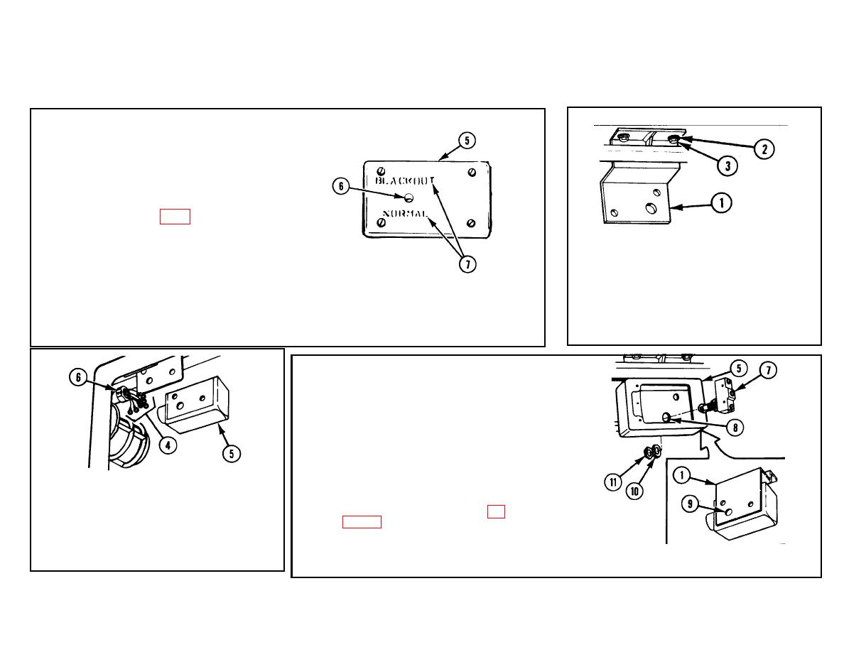
COVER (5).
a. Drill one 0.47-in. (1.19-cm) hole (6) as
illustrated.
b. Stencil black lettering (7) in 0.25-in.
(0.64-cm) letters using black semigloss
lacquer (item 10, app D) as illustrated.
NOTE
For clarity. existing wires not
mentioned in text have been
removed.
1
MOUNTING BRACKET (1). Install two flat
washers (2) and two hex head capscrews
(3).
4
MICROSWITCH (7). Install in hole (8) in
back of switchbox (5) and through hole (9)
in mounting bracket (1).
NOTE
Adjust microswitch so that
plunger protrudes enough so
when door bolt is closed the
plunger is depressed, and
when door bolt is open the
2
HARNESS ASSEMBLY (4).
Push into
plunger is released.
For
switchbox (5).
further instructions, refer to
adjustment of microswitch, p
3
CONNECTOR (6). Install in switchbox (5).
3-194.
5
WASHER (10) AND HEX NUT (11).
Install.
3-190
