TM 10-8340-243-13&P
0013
2. Remove strain relief nut (Figure 2, Item 4) from smaller end cap located opposite handle, then
remove end cap (Figure 2, Item 5). Do not loosen jam nut (Figure 2, Item 6).
NOTE
It may be necessary to cut cable ties retaining the end cap.
3. Carefully remove shock (Figure 2, Item 7), using care not to pull on cord (Figure 2, Item 8).
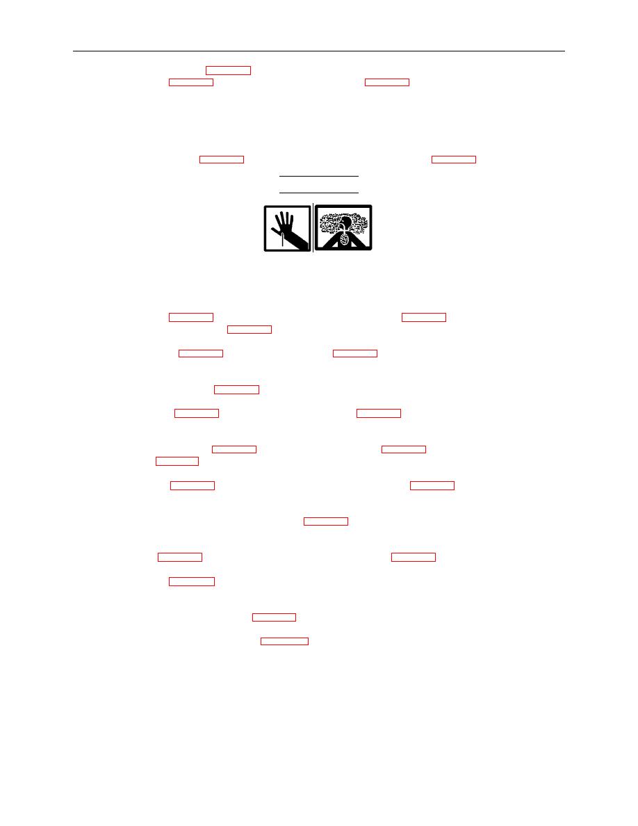
WARNING
If the lamp has shattered within the light assembly, use caution when clearing the glass
from the lamp. Glass shards can cause severe cuts to fingers, and the fluorescent
coating of the bulb may be accidentally inhaled or ingested.
4. Grasp bulb puller (Figure 2, Item 9) and gently but firmly pull bulb (Figure 2, Item 10) out of socket
and remove from outer tube (Figure 2, Item 11). Take care since bulb is tightly wedged in socket.
5. Remove bulb puller (Figure 2, Item 9) from old bulb (Figure 2, Item 10) and dispose of bulb IAW unit
SOP. If old bulb is not broken, there is a vacuum inside and breaking the bulb can be dangerous.
6. Clean inside of outer tube (Figure 2, Item 11) if necessary.
7. Install bulb puller (Figure 2, Item 9) on replacement bulb (Figure 2, Item 10) as shown. This will
assist in removing bulb the next time.
8. Slide the replacement bulb (Figure 2, Item 10) with bulb puller (Figure 2, Item 9) into outer tube and
align so pins (Figure 2, Item 12) will intersect with receiver holes in socket.
9. Gently push bulb (Figure 2, Item 10) down into socket and seat pins (Figure 2, Item 12) in receiver
holes.
10. Plug light in and activate switch. Ensure bulb (Figure 2, Item 10) is seated properly and that it
illuminates. Switch light OFF and disconnect power.
11. Replace shock (Figure 2, Item 7), using care not to pull on cord (Figure 2, Item 8) or screen.
12. Replace end cap (Figure 2, Item 5), making certain cap is fully seated in groove of tube. Secure in
place with cable tie, if necessary.
13. Install and tighten strain relief nut (Figure 2, Item 4).
14. Install light IAW procedures given in WP 0005.
0013-2


