TM 10-7310-281-13&P
MODERN BURNER UNIT (MBU)
0002 00
LOCATION AND DESCRIPTION OF MAJOR COMPONENTS
0002 00-3
DESCRIPTION OF SYSTEM COMPONENTS
The associated components of the MBU are illustrated and described below:
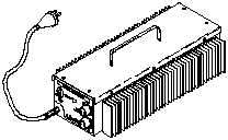
Power Converter. Converts 120 V AC + 4% to 24 V
DC. Four MBUs can be powered through each of two
output connectors. Refer to the appropriate power
configuration schematic beginning on page 0003. A
power switch turns the unit on and off. The converter is
capable of operating within the same environmental
conditions as the MBU.
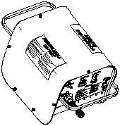
Battery Pack. Contains two sealed lead acid
batteries and an internal charger. It provides the
electrical storage to start and operate 3 MBUs
simultaneously for 3 hours at 750F, or a 2 hour period
at -250F. The module is rechargeable through the
standard NATO vehicular power connector in 2 hours
at an ambient temperature of 750F, and in three hours
at -250F. The battery charger circuit prevents
overcharge. A three position function switch controls
the charging function as well as the voltage supplied
to the output connector. Indicator lights show the state
of the battery charge. The batteries and charger are
assembled in an aluminum frame with handles and a
cover. The pack is capable of operating within the
same environmental conditions as the MBU.
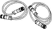
24V DC Power Cables. Two types of power cable
extensions are furnished, a 15ft length for use in the
MKT, and a 25ft length for use with all other systems.
In addition, two types of two-branch power cables, one
for exclusive use in the MKT and a four-branch power
cable are furnished to connect the MBUs to either one
of the power cable extensions, or directly to the power
converter.
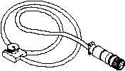
NATO Adapter Cable . To facilitate the connection
between a vehicle and the battery module, or between
a vehicle and the MBUs directly, a 25ft adapter cable
is provided that is compatible with the power-in
receptacle of the MBU and battery module, as well as
the vehicular output connector.