TM 10-5411-200-14
T.O. 35E4-177-1
4-32.
(cont)
(b) Operation II - Knock out drilled pin and remove upper
portion of pin and lock collar.
(See page 4-187)
(c) Operation III - Counterbore sleeve.
(See page 4-188)
(d) Operation IV - Knock out counterbored sleeve and remove
head of sleeve.
(See page 4-189)
NOTE
The illustration of the operations for removal show
a countersunk blind bolt.
The removal of a pro-
truding head blind bolt is the same.
A micro-limit
tool is used with the counterbore cutter in Operation
III to control the depth of the cut.
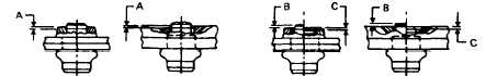
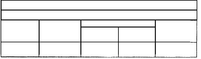
TABLE I
VISUAL INSPECTION TABLE
Collar
Lock Position
Minimum
Rivet
Position
“B” max.
“C” max.
Blind Head
Dia.
“A” max.
above
below
Diameter
3/16”
.022”
.012”
.012”
.238”
1/4”
.029”
.015”
.015”
.315”
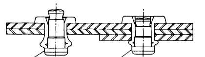
INSPECTION OF
LOCKING COLLAR
INSPECTION OF
POSITION
PIN POSITION
BOLT TOO LONG
BOLT TOO SHORT
PIN WILL PROTRUDE
PIN WILL EXTEND
TOO FAR
TOO FAR IN HEAD
A
- Maximum allowable distance of locking collar
head.
B
- Maximum allowable distance of top of land on
c
- Maximum allowable distance of top of land on
4-152
above or below fastener
pin above fastener head.
pin below fastener head.