
TM 10-5410-221-14/1
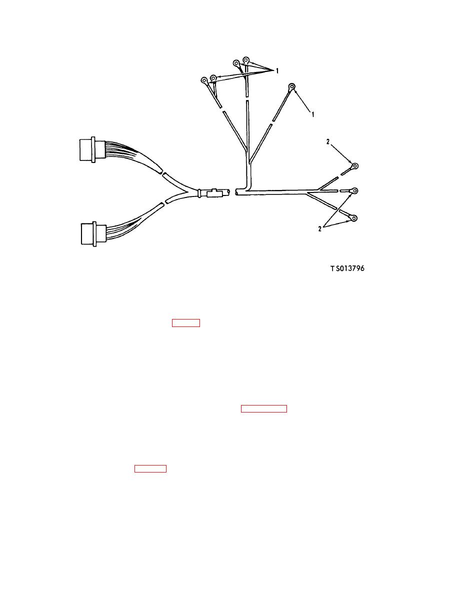
1. Terminal (5)
2. Terminal (3)
Figure 6-11. Surgical and Air Lock Lights Harness Assembly (TS 013796)
from terminal boards (items 28, 38 and 45, fig. 6-7,sheet
NOTE
2 of 5) inside power distribution box.
Cuts or abrasions of harness
(2) Remove cover from raceway adjacent to
assemblies may be due to sharp edges
power out panel and remove clamps securing the
of electrical race was interference with
harness to the raceway.
other
components
or
improper
NOTE
handling.
The cause shall be
Tag or otherwise identify electrical
determined and eliminated before
leads as to connection point for aid at
installation of the harness assemblies.
installation.
d. Assembly. Assemble harness assembly using
(3) Remove nuts, washers and screws securing
the surgical and air lock lights harness and connector
Install terminals
assembly (7, FO-3) (located in back of manual) to the
(1) on wires and crimp to secure.
output assembly.
(2) Install terminals (2) on wires and crimp to
(4) Pull the surgical and air lock lights harness
secure.
e. Test. Use a continuity light, multimeter (para 11-2)
assembly from the shelter.
b. Disassembly.
or other continuity checking device to check wiring
(1) Remove terminals (1, fig. 6-11).
continuity. Continuity must exist between end fittings on
(2) Remove terminals (2).
individual wires. Continuity must not exist between
c. Repair. If possible, straighten any bent connector
connector pins or between connector pins and connector
pins. Inspect wires for abrasions and cuts of insulation.
shell. If test indicates a defective connector or wire,
Minor cuts and abrasions are acceptable and may be
replace the harness assembly.
f. Installation. Install harness assembly as follows:
repaired by wrapping with vinyl tape. Replace harness
assembly if individual wires are cut or otherwise
damaged.
6-19
