TM 9-2330-275-14&P
CHAPTER 2
OPERATING INSTRUCTIONS
Section I. DESCRIPTION AND USE OF OPERATOR’S
CONTROLS AND INDICATORS
Page
Paragraph Title
Number
Controls and Indicators . . . . . . . . . . . . . . . . . . . . . . . . . . . . . . . . . . . . . . . . . . . . . . . . . . . . . . . . . . . . . . . . . . . .. . . . . . . . . . . . . .2-1
General . . . . . . . . . . . . . . . . . . . . . . . . . . . . . . . . . . . . . . . . . . . . . . . . . . . . . . . . . . . . . . . . . . . . . . . . . . . . . . . . . . . . . . . . . .. . . . . . . . . . . . . 2-1
2-1.
GENERAL.
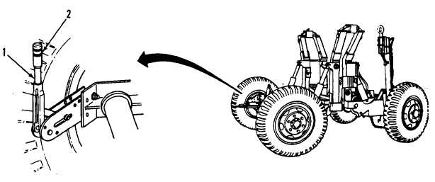
This section shows the location and function of the controls and indicators for the M689, M832, and M840 Dolly
Sets. Review this section thoroughly before operating the dolly set.
2-2. CONTROLS AND INDICATORS.
Key
Component
Description
1
Handbrake Lever
Applies handbrake.
2
I Adjustment Knob
I Adjusts handbrake cable tension.
2-1

