TM 9-2330-275-14&P
Table 4-1. Unit Troubleshooting Chart (con’t).
ELECTRICAL SYSTEM (con’t).
5. SERVICE STOPLIGHTS AND TAILLIGHTS
INOPERATIVE.
Initial Setup:
Equipment Conditions:
Tools and Test Equipment:
Dolly set parked on level surface.
l General mechanic’s tool kit
l Dolly set coupled to towing vehicle with towing
l Common no. 1 shop set
vehicle parking brake applied (pars 2-14).
l Multimeter
NOTE
l Instead of using multimeter for
voltage check, STE/lCE TEST no.
89 may be performed.
l Instead of using multimeter for
continuity check, STE/lCE TEST
no. 91 may be performed.
l Perform pin-to-pin continuity
checks on intervehicular cable
(IVC) before any other tests to
ensure there are no broken wires
internal to IVC. If any tests fail,
replace IVC before proceeding.
This procedure applies to both
taillights.
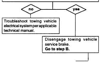
A. Set towing vehicle light switch to SER DRIVE.
Turn towing vehicle master switch OFF. Dis-
connect IVC from dolly distribution box. Engage
service brake on towing vehicle. Place multi-
meter red lead on IVC connector pin E, and
ground black lead by placing on pin L. Turn
towing vehicle master switch ON and check pin
E for battery voltage. Repeat for pins B and J.
IS BATTERY VOLTAGE PRESENT?
Continued on next page
4-19


