
TM 10-5410-221-14/1
3. AN/URM-105. Read the upper, black,
(b) With all three multimeters, connect one probe
to one side of the circuit and the other probe to the other
straight-lined portion of the "AC and DC volts" scale for-
side. The example (fig. 11-15) shows 115 volts AC
the range the selector switch is set at.
being measured across an AC light circuit.
(c) Read meter on the "AC" scale. Figure 11-16
Switch Setting
Scale
shows a reading of 115 volts on all meters.
1000 DC Volts ....................... 0-10 (and multiply by 100)
100 DC Volts ......................... 0-10 (and multiply by 10)
20 DC Volts ........................... 0-10
1 DC Volt ............................... 0-10 (and divide by 10)
Thus, the meter (fig. 11-11) is showing the following
readings:
d. Using the AC Volts Scale. The AC volts scale is
used to measure the AC voltage found in various places
on the unit.
(1) Before using the multimeter to measure AC
voltage, do the following steps that match the multimeter
you have.
(a) AN/URM-105. Set meter switch to "1000
AC volts" (fig. 11-12).
(b) TS-352B/U.
1. Set "FUNCTION" switch to "AC volts".
("RANGE" switch can be at any setting.) (A, fig. 11-13.)
2. Put black lead in "-DC/+AC/OHMS" jack
(B, fig. 11-13).
3. Put lead in "250V" jack on right side of
meter.
(c) Simpson 160 (fig. 11-14).
1. Put black lead in "COM-" jack.
2. Put red lead in "+" jack.
3. Set selector switch to "V/AC 250" position.
(2) To measure 115 AC voltage, do the following
steps:
(a) Set up multimeter (fig. 11-15).
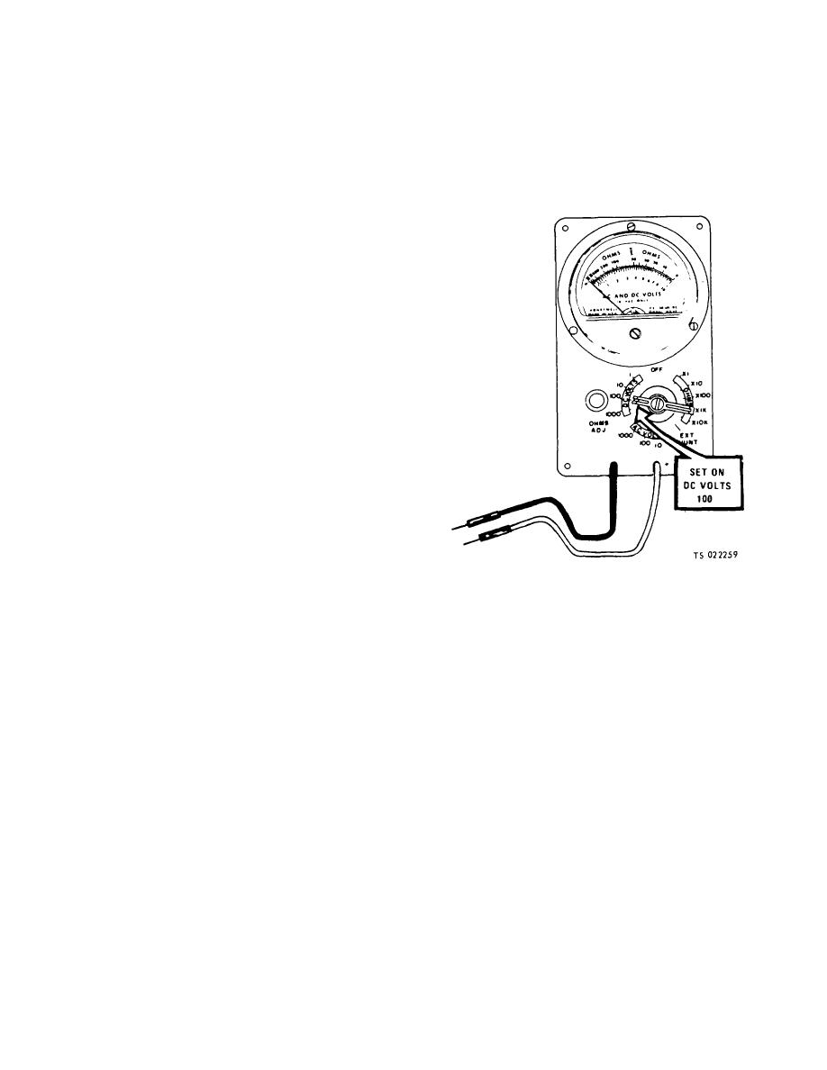
Figure 11-7. DC Volts Scale (Sheet I of 3) (TS 022259)
11-8
