
TM 10-5410-221-24
1
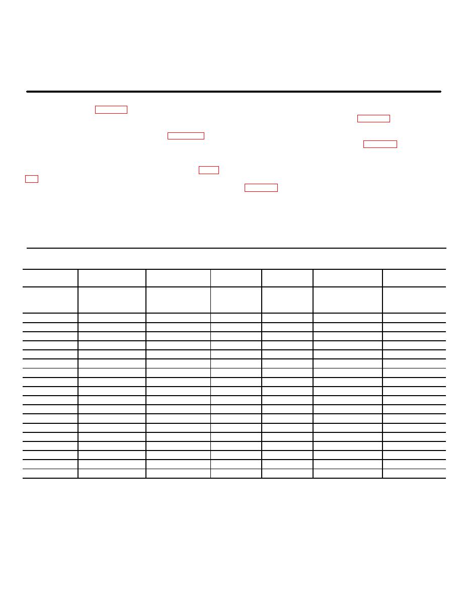
Terminal (7)
4
Screw (4)
7
Connector
2
Nut (4)
5
Cover plate
8
Wire (AN16)
3
Washer (8)
6
Sleeving, insulation
9
Wire (AN12)
Figure 6-18-Continued.
assemblies as required to replace damaged components
wiring schematic and table 6-1 for wire chart.
by removing applicable terminals (table 6-1).
b. Removal. Remove loose wires according to
d. Assembly. Assemble loose wire assemblies in
defective circuit involved referring to table 6-1 for
reverse order of disassembly using table 6-1 as a guide,
terminal identification and observing the following.
install appropriate terminal and crimp to secure.
(1) Remove applicable access cover plates
e. Test. Use a continuity light, multimeter or other
and remove the appropriate electrical leads using table
continuity checking device to check continuity of wiring
(2) Pull the loose wire assembly from the
shelter electrical raceways.
wires. Replace wire if continuity does not exist.
c.
Disassembly. Disassemble loose wire
Component and terminal identification
Terminal
Terminal
From
item No.
To
item No.
No. req'd
Wire No.
Wire item no.*
--
4
--
4
24
Jumper (con-
1
venience
J25-L2
4
J23-L2
4
1
X663B12
1
J23-L2
4
CB13-L3
4
1
X663A12
1
J25-COM
4
J23-COM
4
1
X662B12
1
J23-COM
4
CB13-L1
4
1
X662A12
1
J27-COM
4
CB12-L1
4
1
X661B12
1
J9-COM
4
CB12-L1
4
1
X661A12
1
J27-L1
4
CB12-L3
4
1
X660B12
1
J9-L1
4
CB12-L3
4
1
X660A12
1
J29-COM
4
CB5-L1
4
1
X659B1 2
i
J11-COM
4
CBS-L1
4
1
X659A12
1
J29-L1
4
CB5-L,
4
1
X658B12
1
J11-L1
4
CB5-L3
4
1
X658A12
1
.T26-COM
4
J24-COM
4
1
X657B12
1
J24-COM
4
CB4-L1
4
1
X657A12
1
J26-L2
4
J24-L2
4
1
X656B12
1
J24-L2
4
CB4-L3
4
1
X656A12
1
LT5-1
6
LT4-1
6
1
L480B16
2
LT4-1
6
S1-4
3
1
L480A16
2
6-25

