
TM 10-5410-221-24
nector and three electrical leads to provide
(3) back to expose soldered wire connections
interconnecting between lights LT and LT7 and between
to connector (4). Unsolder connections and remove
LT3 and LT5.
wires (5) from connector. Remove sleeving (3).
d. Repair.
b. Removal.
If possible, straighten any bent
connector pins. Inspect wires for abrasions and cuts of
(1) Disconnect female harness connector (13,
insulation. Minor cuts and abrasions are acceptable and
14) from receptacle boxes J21 and J22 o the shelter
may be repaired by wrapping with vinyl tape. Replace
ceiling.
individual wires if cut or otherwise damaged. Inspect
(2) Remove screws (1, fig. 6-10) an cover
connector for any conductive wire or debris between
plates (2) from receptacle boxes and re move screw (3)
connector pins which may cause a short and remove if
and bracket (4). Separate male harness (8) from
required.
bracket (4) by removing nut (5), washer (6) and screw
(7).
Note. Cuts or abrasions of harness assemblies
(3) Disconnect terminals (1, fig. 6-9 from light
may be due to sharp edges of electrical raceways,
assemblies LT3 and LT7 (par 2-30).
interference with other components or improper
(4) Pull harness assemblies (13, 14 fig 6-1)
handling. The cause shall be determined and eliminated
from the electrical wiring raceways.
c. Disassembly.
before installation of the harness assemblies.
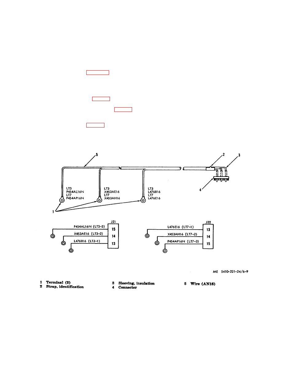
(1) Remove terminals (1, fig. 6-9).
(2) Remove identification strap (2).
Slide
insulation sleeving
Figure 6-9. Fluorescent lights male harness assembly.
6-10

