
TM 10-5410-221-24
solder that conforms to Federal Specification QQ-571.
wires. Continuity must not exist between connector pins
Slide insulation sleeving (4, 5) over soldered connection
or between connector pins and connector shell. If
points.
continuity does not exist between end fittings on
individual wires, replace wire or connector.
Note. Install wires on connector pins accord- ing
g. Installation. Install female harness assemblies in
to figure 6-7. If wires are replaced, mark wire location
reverse order of removal using figure 6-18 as a guide for
number from removed wire onto replacement wire.
terminal identification and figure 1-7 for wiring schematic.
(2). Install terminals (1, 2) on wires and crimp
to secure. (3) Install hood (8) on receptacle (6).
Fluorescent Light Male Harness
Assemblies
f. Test. Use a continuity light, multimeter or other
continuity checking device to check continuity of wiring
a. General. The male fluorescent light harness
assemblies (13, 14, fig. 6-1) consist of a male con-
individual
.
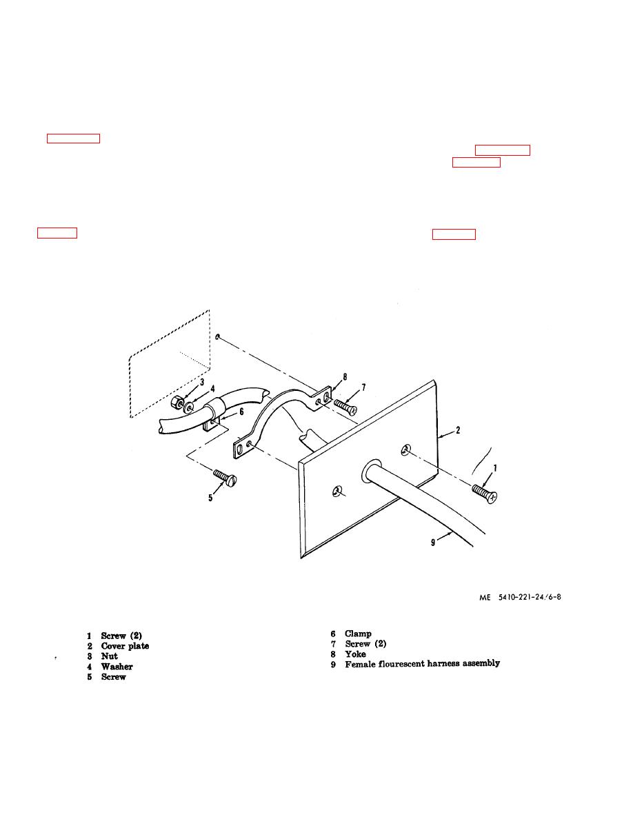
Figure 6-8. Fluorescent lights junction box disassembly.
6-9

