
TM 10-5410-221-14/1
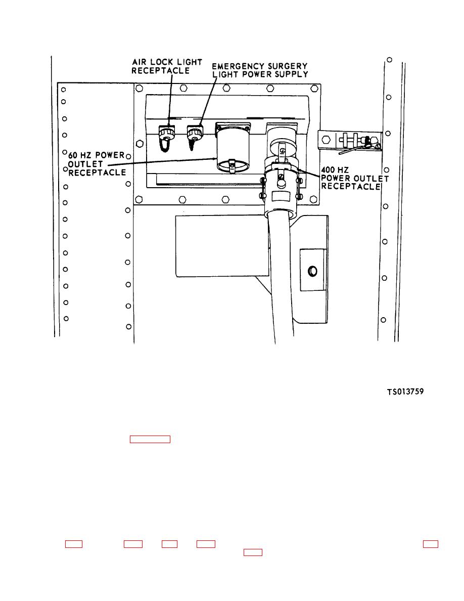
Figure 4-15. Power Output Panel Assembly (TS 013759)
d. Installation. Install fluorescent light -assembly in
b. Panel Assemblies Test Check continuity of input
reverse order of removal using figure 4-12 as a guide.
and output connectors and cables using a continuity
light, multimeter or other continuity checking device.
4-23. Power Input
and
Power
Output
Panel
NOTE
Assemblies
Refer any defects found during the
above continuity checks to direct
a. General. The input and output panel assemblies
support level maintenance.
consist of a 400 Hertz input and output connectors and a
4-24. Power Distribution Panel Assembly
60 Hertz input and output connectors. The input panel
assembly is mounted adjacent to the water box
a. General. The power distribution panel assembly is
assembly at the bottom center of the front fixed end
mounted above the rear access door. It contains the
panel. The output assembly is mounted midway up the
shelter circuit breaker panel, and emergency light,
rear fixed end panel assembly adjacent to the access
terminal boards and wire and harness assemblies (fig.
door
4-69

