
TM 10-5410-221-14/1
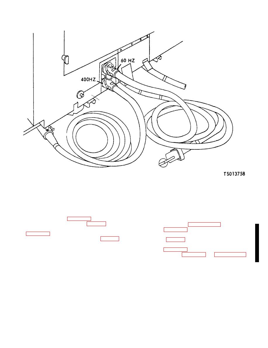
Figure 4-14. Power Input Panel (TS 013i58)
b. Air Lock Light Assembly Test. Check continuity of
NOTE
light assembly using a continuity light, multimeter or
Refer any defects found during above
other continuity checking device.
test to direct support maintenance level.
c. Disassembly.
Disassemble light assembly for
replacement of lamp or guard according to sequence of
4-22. Fluorescent Light Assemblies
index numbers assigned to figure 4-16.
d. Assembly. Assemble guard (4, fig. 4-16) and lamp
a. Removal. Refer to paragraph 4-16a, steps (1) thru
(1) to light assembly in reverse order of disassembly and
(5) and use figure 4-12 as a guide.
using figure 4-16 as a guide.
b. Disassembly.
Disassemble fluorescent light
e. Installation. Install light assembly (5, fig. 4-16) on
assembly (4, fig. 4-12, sheet 1 of 3) to repair or replace
hook in air lock chamber and connect cable assembly to
damaged parts by observing sequence of index numbers
power inlet or outlet panel, whichever is convenient.
assigned to figure 4-12.
c. Assemble. Use figure 4-12 and paragraph 4-16c as
4-21. Convenience Receptacles
a guide and assemble the fluorescent light assembly.
a. Convenience Receptacle Inspect.
Remove
receptacle cover and inspect for damaged or burned
terminals. Replace or repair any damaged receptacle
covers.
b. Convenience Receptacle Test. Check continuity of
receptacle wires using a continuity light, Multimeter (para
11-2), or other continuity checking device.
Change 1 4-68

